


2-1- عيوب مقترنه بتصميم وصلات اللحام Design related
2-2- عيوب ناتجه عن طرق اللحامWelding process related
2-3- عيوب ميتالورجيهMetallographic structure related
2-2- عيوب ناتجه عن طرق اللحامWelding process related
2-3- عيوب ميتالورجيهMetallographic structure related
2-1- عيوب مقترنه بتصميم وصلات اللحام تشمل
2-1-1 عدم محاذاة Misalignment
وهذا يحدث بسبب عدم تطبيق القطعتين بصورة صحيحة كما في الشكل (16)
2-1-1 عدم محاذاة Misalignment
وهذا يحدث بسبب عدم تطبيق القطعتين بصورة صحيحة كما في الشكل (16)
وتظهر في التصوير الشعاعي كما في الشكل (17)
ولعلاج هذه الحالة يجب اعادة التطبيق بصورة جيدة
2-1-2- التغيير في المقاطع وأماكن تركيز الاجهادات الأخرى:
كاستخدام قطعتين مختلفتين بالسمك. ولعلاج هذه الحالة يتم تجليخ نهاية القطعة الاكثر سمك بصورة انسيابية وكما في الشكل(18).
كاستخدام قطعتين مختلفتين بالسمك. ولعلاج هذه الحالة يتم تجليخ نهاية القطعة الاكثر سمك بصورة انسيابية وكما في الشكل(18).
2-2- العيوب الناتجة عن طرق اللحام تشمل
2-2-1- التجاويف Cavities وتسمى ايضاً بالبخبخة (( Porosity
وهي عيب في وصلة اللحام ينتج عن احتباس غازات داخل اللحام اثناء تجمد معدن اللحام. وتأخذ التجاويف عادة الشكل الكروي وتسمى بالمساماتporosities او الشكل الاسطواني ويطلق عليها اسم الثقب الدودي Wormhole كما في الشكل (19).
وهي عيب في وصلة اللحام ينتج عن احتباس غازات داخل اللحام اثناء تجمد معدن اللحام. وتأخذ التجاويف عادة الشكل الكروي وتسمى بالمساماتporosities او الشكل الاسطواني ويطلق عليها اسم الثقب الدودي Wormhole كما في الشكل (19).
2-2-1-1- أسبابها
- تلوث العينة قبل اللحام ( زيت و شحم و طلاء و...)
- تلوث سلك اللحام المستخدم ( زيت و شحم و .....) أو رطوبة
- تلوث الغاز المستخدم في حماية اللحام(CO2,ARGON ) كما في لحام ال( GTAW)
- استخدام سلك لحام غير مناسب للوصلة
- استخدام عملية لحام غير مناسب للوصلة
- عدم إحكام (الدروة) الحماية من الرياح
- قلة خبره من اللحام أسلوب غير مناسب
2-2-1-2- أنواع البخبخة
- البخبخة العشوائية و تحدث بدون انتظام أثناء اللحام Uniformly Scattered
- البخبخة العشوائية و تحدث بدون انتظام أثناء اللحام Uniformly Scattered
- البخبخة المتمركزة و تحدث بدون انتظام أثناء اللحام Cluster Porosity
- بخبخة أسطوانية الشكل ممتدة و تحدث غالبا في الغرز Worm Hole
- بخبخة بطول اللحام على خط واحد في الغرز Aligned Porosity
2-2-1-3- طريقة اكتشافه
- التصوير بالأشعة (جاما أو اكس)
- افضل طريقه وأدق الكشف بالموجات فوق الصوتية
2-2-2- العوالق الصلبة Solid Inclusion
العوالق الصلبة هي عيب في خط اللحام بسبب انحصار مواد صلبة غريبة ( شوائب ) داخل اللحام وهو ناتج عن انصهار سلك اللحام أو ال (Powder)
2-2-2-1- أسبابه:
العوالق الصلبة هي عيب في خط اللحام بسبب انحصار مواد صلبة غريبة ( شوائب ) داخل اللحام وهو ناتج عن انصهار سلك اللحام أو ال (Powder)
2-2-2-1- أسبابه:
- التنظيف غير الجيد لطبقة الخبث المتكونة فوق الدرزة وذلك قبل لحام الطبقة التالية.
- وجود شواب صلبة بمنطقة اللحام قبل اللحام.
- أسلوب لحام خاطئ او عدم ضبط زوايا اللحام
2-2-2-2- أنواعه
- شوائب متصلة بشكل طولي متصلبة لم يتم أزالتها عند إضافة طبقه لحام تالية
Elongated Slag Lines
Elongated Slag Lines
- شوائب عشوائية بين طبقات اللحام تصلدت أثناء اللحام ولم يتم إزالتها قبل إضافة الطبقة التالية لها
Inter Pass Slag Inclusions
Inter Pass Slag Inclusions
- شوائب متصلة في شكل خطين في اتجاه طولي متوازيين تقريبا Wagon Tracks
2-2-2-3- طريقة اكتشافه:
- التصوير بالأشعة (جاما أو اكس)
- الكشف بالموجات فوق الصوتية
- التصوير بالأشعة (جاما أو اكس)
- الكشف بالموجات فوق الصوتية
2-2-3- نقص في الغرز ( النفاذية ) Lack of Penetration ( LOP
2-2-3-1- انواعه
- نقص غرز مستمر لمسافةIncomplete or Lack of Penetration ( LOP )
2-2-3-1- انواعه
- نقص غرز مستمر لمسافةIncomplete or Lack of Penetration ( LOP )
- ثقب في الغرز Burn Through
2-2-3-2- الأسباب :
- سلك لحام غير مناسب.
- فتحة الجذر في الوصلة التقابلية غير مناسبة اما كبيرة او صغيرة
- قلة خبره و عدم اهتمام من اللحام.
- اندفاع تيار هواء أثناء اللحام.
- سلك لحام غير مناسب.
- فتحة الجذر في الوصلة التقابلية غير مناسبة اما كبيرة او صغيرة
- قلة خبره و عدم اهتمام من اللحام.
- اندفاع تيار هواء أثناء اللحام.
2-2-3-3- طريقة اكتشافه
- التصوير بالأشعة (جاما أو اكس).
- الكشف بالموجات فوق الصوتية
2-2-4- نقص في الانصهار Incomplete Fusion
النقص في الانصهار هو احد عيوب اللحام التي تصف عدم اكتمال انصهار سلك اللحام مع المعدن الاساس.
2-2-4-1- الأسباب :
- شدة التيار منخفضة
- سرعة اللحام زائدة عن الحد الصحيح.
- سلك لحام غير مناسب قطر اكبر من المطلوب
- عدم نظافة سطح المعدن قبل اللحام وعدم ازالة طبقة الصدأ الثقيلة من على سطح المعدن بالكامل.
- وجود زيوت او شحوم او دهان على سطح المعدن.
- قلة خبره و عدم اهتمام من اللحام و استخدام تيار اقل من المطلوب لحدوث الاندماج
- شوائب صلبة بمجرى او منطقة اللحام بسبب اندفاع تيار هواء أثناء اللحام.
2-2-4-2- أنواعه:
- وجود فراغ بين خط اللحام والمعدن الاساس
- وجود فراغ بين خط اللحام والمعدن الاساس
- درجة الحرارة لم تكن كافية لإكمال عملية انصهار واندماج خط اللحام مع المعدن الاساس.
- وجود مادة غريبة بين خط اللحام والمعدن الاساس
- عدم انصهار بين طبقات اللحام و بعضهاInter Pass Cold Lap
يعد عيب النقص في الانصهار من العيوب الخطيرة التي يجب اصلاحها وخصوصاً عندما يكون اللحام مصمما ًللخدمة في الظروف الباردة او يكون معرضاً للتحميل التصادمي او التحميل الدوري (اجهادات الكلال ( Fatigue Stress) مثل المنشآت المعدنية التي تتعرض للرياح.
2-2-4-3- طريقة اكتشافه
- الكشف بالموجات فوق الصوتية
- الكشف بالموجات فوق الصوتية
2-2-5- الشكل غير التام Imperfect Shape
الشكل غير التام لخط اللحام هو عيب في الشكل الظاهر لخط اللحام والمنطقة المجاورة له.
الشكل غير التام لخط اللحام هو عيب في الشكل الظاهر لخط اللحام والمنطقة المجاورة له.
2-2-5-1- القطع (النحر) السفليUnder Cut
هو عيب سطحي يظهر كمجرى او اخدود في المعدن الاساس وذلك مباشرة على طول حافة خط اللحام
هو عيب سطحي يظهر كمجرى او اخدود في المعدن الاساس وذلك مباشرة على طول حافة خط اللحام
- انواعه:
- قطع خارجي ومن الاعلىExternal or Crown Undercut
- قطع خارجي ومن الاعلىExternal or Crown Undercut
- قطع داخلي (في الجذر)Internal or Root Undercut
- أسبابه :
- استخدام أمبير مرتفع
- سرعة اللحام بطيئة
- استخدام سلك لحام غير مطابق
- طريق اكتشافه:
- التصوير بالأشعة (جاما أو اكس)
- الكشف بالموجات فوق الصوتية
- بالنظر إن أمكن ذلك
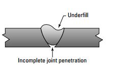
2-2-5-2- نقص في التعبئة Lack of filling (Under Fill)
هو عدم اكتمال اللحام بالحجم المطلوب (حسب المواصفات) كما في الشكل
- استخدام أمبير مرتفع
- سرعة اللحام بطيئة
- استخدام سلك لحام غير مطابق
- طريق اكتشافه:
- التصوير بالأشعة (جاما أو اكس)
- الكشف بالموجات فوق الصوتية
- بالنظر إن أمكن ذلك
2-2-5-2- نقص في التعبئة Lack of filling (Under Fill)
هو عدم اكتمال اللحام بالحجم المطلوب (حسب المواصفات) كما في الشكل
2-2-5-3- التراكب Overlap
هو عيب في اصبع الحام ناجم عن تدفق معدن اللحام على سطح المعدن الرئيسي دون الانصهار والاندماج معه.
هو عيب في اصبع الحام ناجم عن تدفق معدن اللحام على سطح المعدن الرئيسي دون الانصهار والاندماج معه.
2-2-5-4- دعم مبالغ فيه (تقوية اللحام الزائدة)Excess weld reinforcement
2-2-6- عيوب مختلفة
2-2-6-1- عين السمكة (Fisheye) :
2-2-6-1- عين السمكة (Fisheye) :
تظهر على السطح في وصلة اللحام وقد تون فجوة او تضمنات لشوائب محاطة بمساحة مستديرة لامعة. وغالباً ما تحدث عند نهاية سلك اللحام0
2-2-6-2- الانعزال (Segregation) :
وهو عدم التجانس في توزيع العناصر السبائكية أو الشوائب الدخيلة الذى يحدث أثناء تجمد وصلة اللحام حيث يميل الحديد الى التصلب اسرع من بقية العناصر للسبيكة مما يؤدي الى تجمع العناصر الاخرى في وسط السبيكة وبالتالي يؤدي الى حدوث تشققات.
وهو عدم التجانس في توزيع العناصر السبائكية أو الشوائب الدخيلة الذى يحدث أثناء تجمد وصلة اللحام حيث يميل الحديد الى التصلب اسرع من بقية العناصر للسبيكة مما يؤدي الى تجمع العناصر الاخرى في وسط السبيكة وبالتالي يؤدي الى حدوث تشققات.
2-2-6-3- طرطشه أو ترشاش (Spattering ) :
اجزاء متطايره من سلك اللحام خارج معدن اللحام المترسب ولا تشكل جزء منه وتحدث بسبب نفخ القوس مما يسبب تناثر قطرات معدن المليء حول خط اللحام .
- اسبابها
- الاختيار الخاطئ للألكترود.
- الاختيار الخاطئ للتيار.
- اسلوب الحام غير المناسب.
- للتقليل من حدوث الطرطشة يمكن اتباع التعليمات التالية:
- استعمال التيار المتردد AC
- المحافظة على طول قوس مناسب
- استخدام نوع الألكترود السليم حسب شدة التيار ووضع اللحام.
- الاختيار الخاطئ للألكترود.
- الاختيار الخاطئ للتيار.
- اسلوب الحام غير المناسب.
- للتقليل من حدوث الطرطشة يمكن اتباع التعليمات التالية:
- استعمال التيار المتردد AC
- المحافظة على طول قوس مناسب
- استخدام نوع الألكترود السليم حسب شدة التيار ووضع اللحام.
2-2-6-4- تشريز أو احتراق القوس(Arc strikes or Arc burns) :
ينتج عن اعاده انصهار موضعي لمعدن الاساس أو المنطقة المتأثرة حراريا أو سطح اللحام بسبب خطأ في التعامل مع القوس (تشريز).
ينتج عن اعاده انصهار موضعي لمعدن الاساس أو المنطقة المتأثرة حراريا أو سطح اللحام بسبب خطأ في التعامل مع القوس (تشريز).
2-2-6-5- Metallic Inclusion
هي شوائب معدنية (تنجستن) تحدث أثناء اللحام بطريقة ال GTAW , PAW
هي شوائب معدنية (تنجستن) تحدث أثناء اللحام بطريقة ال GTAW , PAW
سبب هذا العيب التصاق التنجستن في الوصلة أثناء اللحام
2-3- عيوب ميتالورجيه Metallographic structure related
تهتم ميتالورجيا اللحام بدراسة تأثير اللحام على المعادن من حيث الخواص الفيزيقية والميكانيكية والتركيب الكيميائي. ومن أساسيات ميتالورجيا اللحام البنية المجهرية لوصله اللحام والتي تؤثر في الخواص الميكانيكية - تغيرات اللحام مثل الدورة الحرارية - التفاعلات الكيميائية في المنطقة المنصهرة - العناصر السبائكية - التركيب الكيميائي لمساعدات الصهر وكل هذه العوامل تؤثر بصفه أساسيه في البنية المجهرية لكل من معدن اللحام والمنطقة المتأثرة بالحرارة.
تهتم ميتالورجيا اللحام بدراسة تأثير اللحام على المعادن من حيث الخواص الفيزيقية والميكانيكية والتركيب الكيميائي. ومن أساسيات ميتالورجيا اللحام البنية المجهرية لوصله اللحام والتي تؤثر في الخواص الميكانيكية - تغيرات اللحام مثل الدورة الحرارية - التفاعلات الكيميائية في المنطقة المنصهرة - العناصر السبائكية - التركيب الكيميائي لمساعدات الصهر وكل هذه العوامل تؤثر بصفه أساسيه في البنية المجهرية لكل من معدن اللحام والمنطقة المتأثرة بالحرارة.
2-3-1- الشقوق (الشروخ) CRACKS
هي عيب من عيوب وصلات اللحام تمتاز بنا طرفاها حادان وبأن نسبة الطول الى فتحة الشق عالية ( شكل انسيابي ) كما موضح بالشكل
هي عيب من عيوب وصلات اللحام تمتاز بنا طرفاها حادان وبأن نسبة الطول الى فتحة الشق عالية ( شكل انسيابي ) كما موضح بالشكل
الشكل الانسيابي للشقوق يجعلها من اخطر انواع العيوب لأنها:
- يمكنها التحرك والانتشار حيث ان شكلها الانسيابي يعطيها القدرة على التحرك باقل طاقة ممكنة.
- تسبب تقليل خطير في قوة درزة اللحام.
- تسبب في حدوث انهيار فجائي.
لذا فان الشقوق يجب اصلاحها ولا يتم قبول اللحام في حالة وجودها. وتزداد خطورة الشقوق مع التحميل التصادمي وكذلك عندما يكون اللحام مصمماً للخدمة في ظروف باردة.
2-3-1-1- اسبابه:
تتولد الشقوق عادة بسبب تعرض اللحام لاختلافات سريعة في درجات الحرارة مثل:
- عمليات التبريد السريع لوصلة اللحام
- عدم التسخين المسبق لمنطقة اللحام.
- عدم تتابع عمليات لحام الوصلة وترك الدرزة تبرد قبل اكمال اللحام.
وهناك اسباب اخرى مثل:
- استخدام سلك غير مطابق
- استخدام سلك به رطوبة شديدة
- تجهيز العينة غير مطابق
- عدم تسخين على حسب المواصفات
- نقص في قابلية المعدن للحام
- خضوع اللحام لإجهادات شديدة أثناء وبعد اللحام
- حرارة عالية أثناء اللحام
- أعادة إصلاح اللحام اكثر من مره لنفس الجزء
- تلوث الوصلة قبل اللحام ( الشنفرة ) دهان أو زيت أو شحوم أو.......
- ضيق الشنفرة مقارنة بالثخانة
- أسلوب اللحام خاطئ ( عرض طبقة اللحام كبير )
- عدم انتظام التيار والفولت وسرعة اللحام أثناء اللحام (Heat Input)
- عدم خضوع الوصلة للمعالجة الحرارية المطلوبة على حسب المواصفات
- معدل تبريد سريع للوصلة
2-3-1-2- انواع الشقوق:
الشكل ادناه يبين انواع الشقوق
الشكل ادناه يبين انواع الشقوق
2-3-2- التشققات الهيدروجينية ( المنطقة المتأثرة بالحرارة) Hydrogen Cracking:
وتسمى ايضا الشروخ على البارد وتحدث بعد تجمد معدن اللحام في كل من المنطقة المتأثرة بالحرارة ومعدن اللحام في انواع عديده من الصلب مثل الصلب منخفض التسابك أو الصلب عالي التسابك ولأن هذه الشروخ تحدث تحت كبح فأحيانا يطلق عليها شروخ الكبح كذلك يطلق عليها الشروخ المتأخرة أو المؤجلة لأنها تحدث بعد تجمد اللحام بعدة ساعات أو خلال ايام وتوصف هذه الشروخ ايضا بموقعها مثل شرخ طرفي ، شرخ جذري وشرخ تحت الدرزة.
وتسمى ايضا الشروخ على البارد وتحدث بعد تجمد معدن اللحام في كل من المنطقة المتأثرة بالحرارة ومعدن اللحام في انواع عديده من الصلب مثل الصلب منخفض التسابك أو الصلب عالي التسابك ولأن هذه الشروخ تحدث تحت كبح فأحيانا يطلق عليها شروخ الكبح كذلك يطلق عليها الشروخ المتأخرة أو المؤجلة لأنها تحدث بعد تجمد اللحام بعدة ساعات أو خلال ايام وتوصف هذه الشروخ ايضا بموقعها مثل شرخ طرفي ، شرخ جذري وشرخ تحت الدرزة.
2-3-2-1- أسباب حدوثها :
تحدث نتيجة لانتقال الهيدروجين من معدن اللحام الى المنطقة المتأثرة حراريا . هذا الهيدروجين ناتج من الرطوبة في مستهلكات أو سلك اللحام أو على وجه الوصلة. في بعض المخلفات كالدهان والزيوت أو في طبقه الاكاسيد الموجودة على الوصلة يزيد احتمال التشرخ بزياده ثخانة الوصلة أو زياده المكافئ الكربوني. كذلك هناك عوامل اخرى تساعد على التشرخ على البارد مثل كبر المسافة الجذرية ، عدم كفاية الدخل الحرارى أو أن يكون التسخين المسبق للحام غير كاف ولحامات التبنيط غير منتظمة الحجم أو المسافة أو نتيجة زيادة الاجهادات اثناء التداول بعد اللحام وقبل إجراء المعالجة الحرارية لإزالة الاجهادات.
تحدث نتيجة لانتقال الهيدروجين من معدن اللحام الى المنطقة المتأثرة حراريا . هذا الهيدروجين ناتج من الرطوبة في مستهلكات أو سلك اللحام أو على وجه الوصلة. في بعض المخلفات كالدهان والزيوت أو في طبقه الاكاسيد الموجودة على الوصلة يزيد احتمال التشرخ بزياده ثخانة الوصلة أو زياده المكافئ الكربوني. كذلك هناك عوامل اخرى تساعد على التشرخ على البارد مثل كبر المسافة الجذرية ، عدم كفاية الدخل الحرارى أو أن يكون التسخين المسبق للحام غير كاف ولحامات التبنيط غير منتظمة الحجم أو المسافة أو نتيجة زيادة الاجهادات اثناء التداول بعد اللحام وقبل إجراء المعالجة الحرارية لإزالة الاجهادات.
2-3-2-2- كيفية التعرف عليها:
سطحياً
- بالفحـــــص البصــــــرى أو باستخدام عدسه مكبره.
- باستخدام اختبار الصبغات المتغلغلة PT.
- الحبيبات المغناطيسيةMT.
داخلياً :
- باستخدام الموجات فوق الصوتية UT.
- التصوير بالأشعة بعد 48 ساعة على الاقل من عملية اللحام.
سطحياً
- بالفحـــــص البصــــــرى أو باستخدام عدسه مكبره.
- باستخدام اختبار الصبغات المتغلغلة PT.
- الحبيبات المغناطيسيةMT.
داخلياً :
- باستخدام الموجات فوق الصوتية UT.
- التصوير بالأشعة بعد 48 ساعة على الاقل من عملية اللحام.
2-3-2-3- طريقة الاصلاح :
الشروخ القصيرة المعزولة المتاحة من السطح يمكن إزالتها ثم الاصلاح باللحام - أما في حالة الشروخ الكبيرة أو الشروخ المخفية تحتاج الى استبدال الجزء المعيب وفى حالة اعاده الاصلاح باللحام يراعى إجراء عمليه التسخين المسبق للحام بطريقه صحيحه والتحكم في الدخل الحرارى لتقليل احتمال حدوث هذا العيب ثانيه.
2-3-2-4- الاحتياطات لتفاديها:
يجب اختيار اسلوب اللحام المناسب مع أنواع الصلب التي تظهر تصلداً في المنطقة المتأثرة بالحرارة مع مراعاة العوامل الأتية:
- يجب ان يكون الكترود اللحام من النوع منخفض الهيدروجين وتتم عملية اللحام تحت
سيطرة وتحكم في ظروف اللحام .
- يجب تجفيف الكترود اللحام طبقاً لتعليمات الشركة المنتجة.
- يجب التسخين المسبق لمعدن الاساس وفى حاله الضرورة بحيث ترفع حراره وصلة اللحام
بأكملها للدرجة المطلوبة.
- التحكم في كميه الدخل الحرارى أثناء اللحام وايضاً اثناء التبنيط.
- يجب أن يكون التركيب الكيميائي لمعدن الاساس ضمن الحدود المقبولة في طريقة
اللحام المستخدمة.
2-3-3- التصدع أو الشروخ الصغيرة(Fissures)
مثل الشروخ ولكن فتحاتها ضيقه وسطحيه .
2-3-4- التمزق الرقائقي (Lamellar tear) :
وهو نوع من الشروخ يحدث في معدن الأساس أو المنطقة المتأثرة حرارياً نتيجة للكبح في وصلة اللحام.
وهو نوع من الشروخ يحدث في معدن الأساس أو المنطقة المتأثرة حرارياً نتيجة للكبح في وصلة اللحام.
2-3-5- LAMINATION & DELAMINATION
2-3-5-1- LAMINATION
هو حدوث انفصال داخلي لطبقات المعدن الداخلي ويحدث نتيجة وجود عيب قديم في العينة و بعد عمليات الرفلة أثناء التصنيع يحدث الانفصال.
هو حدوث انفصال داخلي لطبقات المعدن الداخلي ويحدث نتيجة وجود عيب قديم في العينة و بعد عمليات الرفلة أثناء التصنيع يحدث الانفصال.
2-3-5-2- DELAMINATION
هو الانفصال النهائي لطبقات المعدن عند التأثير عليه بإجهادات داخليه حرارية او ميكانيكية و ذلك نتيجة للقطع أو اللحام
هو الانفصال النهائي لطبقات المعدن عند التأثير عليه بإجهادات داخليه حرارية او ميكانيكية و ذلك نتيجة للقطع أو اللحام
- طريقة اكتشافه الكشف بالموجات فوق الصوتية
----------------------------------------------------------------------------------Welding Procedures (overview)
 | |||||||||||||||||||||||||||||||||||||||||||||||||||||||||||||||||||||||||||||||||||||||||||||||||
|
| ||||||||||||||||||||||||||||||||||||||||||||||||||||||||||||||||||||||||||||||||||||||||||||||||
| NDT Technique | Materials applicable | Detection capability | Depth Sizing | Orientation Evaluation | Access problem | Remote Detection | Automated detection |
| Liquid penetrant | All | Surface | No | No | Yes | No | No |
| Ultrasonic | All | Volumetric | Yes | Yes | Limited | Yes | Yes |
| Radiography | All | Volumetric | Yes | Yes | Yes | No | Yes |
| Magnetic Particle | Magnetic | Surface, near-surface | No | No | Yes | No | No |
| Magnetic Fluxleakage | Magnetic | Surface, near-surface | Yes | Yes | No | Yes | Yes |
| Eddy current | Conducting | Surface, near-surface | Yes | yes | Yes | Yes | yes |
| Acoustic Emission | All | Volumetric | Yes | No | No | Yes | Yes |
| Thermo-graphy | All | Surface, near-surface | No | Yes | No | Yes | Yes |
| Visual | All | Surface | No | No | Limited | Yes | Yes |
| XRD | Conducting | Suface Stresses | Yes | No | Yes | No | No |
| Potential drop | Conducting | Surface | Yes | No | Yes | No | Yes |
Engineering and Construction Codes and Standards | ||||||||||||||||||||||||||||||||||||||||||||||||
ASME IX - American Society of Mechanical Engineers | ||||||||||||||||||||||||||||||||||||||||||||||||
| Material (P numbers) will assist the Welding Engineer to complete the Welding Procedure Specification prior to the mechanical testing of the Procedure Qualification Report. | ||||||||||||||||||||||||||||||||||||||||||||||||
|
Welding Defects
Cold Lap | |||
|
| ||
Porosity | |||
|
| ||
Cluster Porosity | |||
|
| ||
Slag inclusion | |||
|
| ||
Incomplete Penetration (IP) or lack of penetration (LOP) | |||
|
| ||
Incomplete fusion | |||
|
| ||
Internal Concavity or Suck Back | |||
|
| ||
Internal or Root Undercut | |||
|
| ||
External or Crown Undercut | |||
|
| ||
Offset or Mismatch | |||
|
| ||
Inadequate Weld Reinforcement | |||
|
| ||
Excess Weld Reinforcement | |||
|
| ||
Cracks | |||
|
| ||
Discontinuities in TIG Welds | |||
Tungsten Inclusion | |||
|
| ||
Oxide inclusions | |||
|
| ||
Discontinuities in Gas Metal Arc Welds (GMAW) | |||
| Whiskers are short lengths of weld electrode wire, visible on the top or bottom su6rface of the weld or contained within the weld. On a radiograph they appear as light, "wire like" indications. | |||
Burn Through | |||
|
| ||


Hands on Quality Control Weld Defects
 |  |  |
|  |  |
 |  |  |
 |  |  |
 |  |  |
 |  |  |
 |
PIPING MATERIAL COLOU
-------------------------------------------------------------------------
Incomplete Penetration
Incomplete penetration happens when your filler metal and base metal aren’t joined properly, and the result is a gap or a crack of some sort. Check out the Figure below for an example of incomplete penetration.
- a common case of incomplete penetration

Welds that suffer from incomplete penetration are weak at best, and they’ll likely fail if you applymuch force to them. (Put simply, welds with incomplete penetration are basically useless.)
Here’s a list of the most common causes of incomplete penetration welding defect.
The groove you’re welding is too narrow, and the filler metal doesn’t
reach the bottom of the joint.
✓ You’ve left too much space between the pieces you’re welding, so they
don’t melt together on the first pass.
✓ You’re welding a joint with a V-shaped groove and the angle of the
groove is too small (less than 60 to 70 degrees), such that you can’t
manipulate your electrode at the bottom of the joint to complete
the weld.
✓ Your electrode is too large for the metals you’re welding.
✓ Your speed of travel(how quickly you move the bead) is too fast, so
not enough metal is deposited in the joint.
✓ Your welding amperage is too low.If you don’t have enough electricity
going to the electrode, the current won’t be strong enough to melt the
metal properly
Incomplete Fusion
Incomplete fusion occurs when individual weld beads don’t fuse together, or when the weld beads don’t fuse properly to the base metal you’re welding, such as in below.
 |
| a textbook example of incomplete fusion |
The most common type of incomplete fusion is called overlap and usually occurs at the toe(on the very top or very bottom of the side) of a weld. One of the top causes is an incorrect weld angle, which means you’re probably holding the electrode and/or your filler rods at the wrong angle while you’re making a weld; if you think that’s the case, tweak the angle a little at a time until your overlap problem disappears.
Here are a few more usual suspects when it comes to incomplete fusion
causes.
✓ Your electrode is too small for the thickness of the metal you’re welding.
✓ You’re using the wrong electrode for the material that you’re welding.
✓ Your speed of travel is too fast.
✓ Your arc length is too short.
✓ Your welding amperage is set too low.
If you think your incomplete fusion may be because of a low welding amperage, crank up the machine! But be careful: You really need only
enough amperage to melt the base metal and ensure a good weld.
Anything more is unnecessary and can be dangerous.
✓ Contaminants or impurities on the surface of the parent metal(the metal
you’re welding) prevent the molten metal (from the filler rod or elsewhere
on the parent metal) from fusing.
Undercutting
Undercutting is an extremely common welding defect. It happens when your base metal is burned away at one of the toes of a weld. To see what I mean, look at Figure.

When you weld more than one pass on a joint, undercutting can occur between the passes because the molten weld is already hot and takes less heat to fill, yet you’re using the same heat as if it were cold. It’s actually a very serious defect that can ruin the quality of a weld, especially when more than 1⁄32 inch is burned away. If you do a pass and notice some undercutting, you must remove it before you make your next pass or you risk trapping slag (waste material — see the following section) into the welded joint (which is bad news). The only good thing about undercutting is that it’s extremely easy to spot after you know what you’re looking for.
Here are a few common causes of undercutting:
✓ Your electrode is too large for the base metal you’re welding.
✓ Your arc is too long.
✓ You have your amperage set too high.
✓ You’re moving your electrode around too much while you’re welding.
Weaving your electrode back and forth is okay and even beneficial, but if
you do it too much, you’re buying a one-way ticket to Undercutting City
(which is of course the county seat for Lousy Weld County).
Slag Inclusions
A little bit of slag goes a long way . . . toward ruining an otherwise quality weld. Slagis the waste material created when you’re welding, and bits of this solid material can become incorporated (accidentally) into your weld, as in Figure . Bits of flux, rust, and even tungsten can be counted as slag and can cause contamination in your welds.

Common causes of slag inclusions include
✓ Flux from the stick welding electrode that comes off and ends up in the
weld
✓ Failure to clean a welding pass before applying the next pass
Be sure to clean your welds before you go back in and apply a second weld bead.
✓ Slag running ahead of your weld puddle when you’re welding a V-shaped
groove that’s too tight
✓ Incorrect welding angle
✓ Welding amperage that’s too low
Flux Inclusions
If you’re soldering or brazing (also called braze welding), flux inclusions can be a real problem. If you use too much flux in an effort to “float out” impurities from your weld, you may very well end up with flux inclusions like those in Figure . (Head to Chapter 13 for more on brazing and soldering.)

If you’re working on a multilayer braze weld, flux inclusion can occur when you fail to remove the slag or glass on the surface of the braze before you apply the next layer. When you’re soldering, flux inclusion can be a problem if you’re not using enough heat. These inclusions are usually closely spaced, and they can cause a soldered joint to leak. If you want to avoid flux inclusions (and believe me, you do), make sure you do the following:
✓ Clean your weld joints properly after each pass.This task is especially
important when you’re brazing.
✓ Don’t go overboard with your use of flux.
✓ Make sure you’re using enough heat to melt the filler or flux material.
Porosity
If you read very much of this book, you quickly figure out that porosity(tiny holes in the weld) can be a serious problem in your welds (especially stick or mig welds). Your molten puddle releases gases like hydrogen and carbon dioxide as the puddle cools; if the little pockets of gas don’t reach the surface before the metal solidifies, they become incorporated in the weld, and nothing can weaken a weld joint quite like gas pockets. Take a gander at Figure for an example of porosity.

Following are a few simple steps you can take to reduce porosity in your
welds:
✓ Make sure all your materials are clean before you begin welding.
✓ Work on proper manipulation of your electrode.
✓ Try using low-hydrogen electrodes.
Cracks
Cracks can occur just about everywhere in a weld: in the weld metal, the plate next to the weld metal, or in any other piece affected by the intense heat of welding. Check out the example of cracking in Figure.

Here are the three major types of cracks, what causes them, and how you can prevent them.
✓ Hot cracks:
This type of crack occurs during welding or shortly after you’ve deposited a weld, and its cause is simple: The metal gets hot too
quickly or cools down too quickly. If you’re having problems with hot cracking, try preheating your material. You can also postheat your material, which means that you apply a little heat here and there after you’ve finished welding in an effort to let the metal cool down more
gradually.
✓ Cold cracks:
This type of crack happens well after a weld is completed and the metal has cooled off. (It can even happen days or weeks after a
weld.) It generally happens only in steel, and it’s caused by deformities in the structure of the steel. You can guard against cold cracking by
increasing the thickness of your first welding pass when starting a new weld. Making sure you’re manipulating your electrode properly, as well as pre- and postheating your metal, can also help thwart cold cracking.
✓ Crater cracks:
These little devils usually occur at the ending point of a weld, when you’ve stopped welding before using up the rest of an
electrode. The really annoying part about crater cracks is that they can cause other cracks, and the cracking can just kind of snowball from
there. You can control the problem by making sure you’re using the appropriate amount of amperage and heat for each project, slowing your
speed of travel, and pre- and postheating.
Warpage
If you don’t properly control the expansion and contraction of the metals you work with, warpage(an unwanted distortion in a piece of metal’s shape) can be the ugly result. Check out an example in Figure.

If you weld a piece of metal over and over, the chances of it warping are much higher. You can also cause a piece of metal to warp if you clamp the joints too tightly. (If you allow the pieces of metal that make the joint to move a little, there’s less stress on them.)
Say you’re welding a Tjoint. The vertical part of the Tsometimes pulls itself toward the weld joint. To account for that movement, simply tilt the vertical part out a little before you weld, so that when it tries to pull toward the weld joint, it pulls itself into a nice 90-degree angle!
The more heat you use, the more likely you are to end up with warpage, so be sure to use only the amount of heat you need. Don’t overdo it. Opting for a slower speed of travel while welding can also help to cut down on warpage.
Spatter
Spatter(small particles of metal that attach themselves to the surface of the material you’re working on.) is a fact of life with most kinds of welding; no matter how hard you try, you’ll never be able to cut it out completely. You can see it in all its glory in Figure 11-5 in Chapter 11.
You can keep spatter to a minimum by spraying with an anti-spatter compound (available at your welding supply store) or by scraping the spatter off the parent metal surface.
These are the 10 most commonly found welding defects. Some new and useful articles are coming soon. So stay tuned.


0 تقييمات:
أكتب تقييمك